
How to Build a Gaming PC: Step-by-Step Assembly Tutorial
Building your first gaming PC represents an exciting milestone that combines technical learning with hands-on creativity. While the process may seem intimidating initially, modern components feature standardized connections and robust designs that make assembly accessible even for complete beginners. This detailed tutorial walks you through every stage of the building process from installing your CPU and applying thermal paste to managing cables and achieving that satisfying first successful boot. Understanding custom gaming PC assembly fundamentals ensures you have the confidence and knowledge to tackle your project successfully.
I built my first gaming PC back in the late 90s and the experience felt genuinely terrifying. Components seemed fragile and compatibility information was scarce. Today’s building experience is dramatically easier with better documentation, standardized parts and countless video resources. The satisfaction of powering on a system you assembled yourself never gets old even after dozens of builds.
Preparation and Tool Requirements
Proper preparation makes building smoother and reduces stress during assembly. Clear a large workspace with good lighting and room to spread out components. A dining table or desk works perfectly. Avoid carpeted areas if possible since static electricity can damage components. If you must work on carpet, touch a grounded metal object frequently to discharge static buildup.
Tool requirements remain minimal for PC building. A Phillips head screwdriver handles 95% of assembly work. Magnetic tip screwdrivers help prevent dropped screws inside the case. Some builders swear by electric screwdrivers though manual ones work fine and provide better control. Wire cutters or scissors help with cable ties. Thermal paste usually comes pre-applied on stock coolers or included with aftermarket coolers.
Organize all components before starting. Unbox everything and verify you received all parts from your orders. Read through motherboard and case manuals to familiarize yourself with layouts and connector locations. This prep work prevents stopping mid-build to hunt for documentation or missing screws. Keep component boxes organized for potential returns if anything arrives defective.
Pro Tip: Take photos during disassembly of packaging and component placement. These reference photos help if you need to repackage items for warranty returns or when troubleshooting connection issues later.
Installing the CPU and Cooler
CPU installation requires care but isn’t as delicate as internet horror stories suggest. Start by opening the motherboard socket. Intel boards use a retention bracket that lifts up while AMD boards feature a simple lever mechanism. Never force the CPU into place. The processor only fits one way determined by notches on Intel chips or a gold triangle marker on AMD processors.
Align the CPU with the socket ensuring markers match. Lower the chip gently into place without applying pressure. It should settle flat on its own. Intel CPUs have a slight wiggle room while AMD chips drop directly into pin holes. Once seated, close the retention mechanism. This requires noticeable force with Intel sockets but don’t panic, that’s normal. AMD levers close easily without resistance.
Thermal paste application causes unnecessary anxiety for new builders. If using a stock cooler the paste comes pre-applied. For aftermarket coolers apply a small pea-sized blob in the CPU center. The cooler mounting pressure spreads paste evenly. More paste isn’t better and excess squeezes out the sides making a mess without improving cooling.
Cooler installation varies by model. Tower air coolers typically use a backplate mounting system. Follow manufacturer instructions carefully as steps differ between brands. Ensure the cooler mounts firmly with even pressure on all corners. Loose mounting causes poor thermal contact and high temperatures. Connect the CPU fan cable to the motherboard header labeled CPU_FAN to ensure proper fan control.
Common Mistake: Forgetting to remove the protective plastic cover from the cooler base before installation. Always check the cooler contact surface for any protective film that needs removal.
Build Order Sequence
1. Install CPU
2. Install RAM
3. Install M.2 SSD
4. Mount Motherboard
5. Install GPU
6. Connect Cables
Follow this sequence for the smoothest building experience
RAM and Storage Installation
RAM installation is straightforward but requires proper slot selection. Motherboards include four slots typically labeled A1, A2, B1 and B2. Installing two RAM sticks requires using the correct slots for dual-channel operation. Consult your motherboard manual but usually slots A2 and B2 (the second and fourth slots) provide optimal configuration.
Line up the notch in the RAM stick with the slot key. This notch sits off-center preventing backwards installation. Open the retention clips on both ends of the slot. Insert RAM at a slight angle then press down firmly on both ends until clips snap into place automatically. The click sound confirms proper seating. RAM requires surprising force so don’t be timid but also avoid excessive pressure that might crack the board.
M.2 SSD installation happens before mounting the motherboard in the case. Locate M.2 slots on the board, usually positioned below the CPU socket or near the bottom edge. Some boards include heatsinks or covers over M.2 slots. Remove these first then insert the SSD at a 30-degree angle into the slot. The drive naturally wants to pop up after insertion. Press it flat and secure with the included standoff screw.
Motherboard and Power Supply Installation
Install the IO shield into the case before mounting the motherboard. This metal plate snaps into the rectangular cutout at the case rear. Press firmly around all edges until it clicks securely in place. Getting it in after motherboard installation requires removing everything and starting over.
Identify standoff locations in your case that align with motherboard mounting holes. Most cases include standoffs pre-installed for ATX motherboards. Verify standoff positions match your board size. Extra standoffs where no mounting holes exist can short-circuit the motherboard by touching traces on the back.
Lower the motherboard carefully into the case aligning it with the IO shield. Thread standoffs through mounting holes and hand-tighten screws in a diagonal pattern. This distributes pressure evenly preventing board flex. Tighten screws snug but not overtight. The goal is securing the board firmly without cracking it or stripping screw threads.
Power supply installation depends on case design. Most modern cases mount PSUs at the bottom with fans facing down pulling cool air through vents. Older cases mount PSUs at the top. Slide the unit into position and secure with four screws from the case exterior. Modular power supplies allow connecting only necessary cables improving airflow and aesthetics.
| Build Step | Time Required | Difficulty Level | Most Common Mistake |
|---|---|---|---|
| CPU Installation | 5 minutes | Easy | Wrong orientation or forcing |
| Cooler Mounting | 10-15 minutes | Medium | Forgetting plastic cover removal |
| RAM Installation | 2 minutes | Easy | Using wrong slots |
| Motherboard Mounting | 10 minutes | Medium | Missing IO shield or wrong standoffs |
| Cable Management | 20-30 minutes | Medium | Forgetting CPU power cable |
| GPU Installation | 5 minutes | Easy | Not removing slot covers |
Graphics Card and Cable Connections
GPU installation comes near the end of the build process. Remove expansion slot covers from the case corresponding to GPU width. Most modern cards occupy two or three slots. The graphics card installs in the topmost PCIe x16 slot closest to the CPU for maximum performance.
Align the GPU with the PCIe slot and case bracket openings. Apply firm even pressure until the card seats fully and the retention clip clicks. Secure the GPU bracket to the case with screws preventing sag and ensuring stable connection. Connect PCIe power cables from the PSU if your GPU requires them. High-end cards need two 8-pin connectors while budget models draw power solely from the PCIe slot.
Cable management separates amateur builds from professional-looking systems. Route cables behind the motherboard tray before connecting them. Modern cases include rubber grommets and Velcro straps facilitating clean organization. Connect the 24-pin ATX power cable and 8-pin CPU power cable first as these provide primary system power.
Front panel connectors handle power buttons, reset switches, USB ports and audio jacks. These tiny headers plug into pins at the motherboard bottom edge. Consult the manual for exact pinout as these vary between manufacturers. The power switch and reset switch have no polarity so orientation doesn’t matter. USB and audio connectors are keyed preventing incorrect connection.
1Power cables: 24-pin ATX, 8-pin CPU, PCIe GPU power
2Data cables: SATA for storage drives
3Fan cables: CPU fan, case fans to motherboard headers
4Front panel: Power switch, USB 3.0, HD audio
First Boot and BIOS Setup
Double-check all connections before the first power-on attempt. Verify the power supply switch is on and the monitor connects to the GPU not the motherboard. Press the power button and watch for signs of life. Fans should spin and lights illuminate. The system beeps once or displays the manufacturer logo indicating successful POST.
Enter BIOS by pressing Delete or F2 during startup. The exact key appears on screen briefly. Modern UEFI BIOS interfaces are mouse-navigable and user-friendly. Verify the system detects all components correctly. Check CPU, RAM and storage show proper capacities and speeds.
Enable XMP or DOCP profiles for RAM to run at advertised speeds instead of default conservative settings. Set boot priority to your SSD for fastest startup times. Save changes and exit BIOS to begin operating system installation. Some systems require multiple restarts during initial setup as components train and optimize settings.
Troubleshooting Tip: If the system doesn’t boot, verify RAM is fully seated and both power cables (24-pin and 8-pin CPU) connect firmly. These account for 90% of first-time build issues.
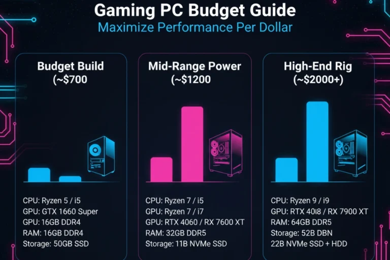
Building a gaming PC provides immense satisfaction and valuable technical knowledge. The process teaches you exactly what’s inside your system and how components interact. This understanding helps with future upgrades and troubleshooting. With your new PC successfully built and running, the next consideration involves ensuring you allocated your budget optimally across components. Learn gaming PC budget optimization strategies to maximize performance per dollar for your next upgrade or helping friends plan their builds.